|
|
|
|
|
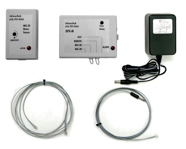
KIT-CA components, MIC-M (noise sensor), DPX-M (time delay), XFORM-1 (power supply), MOD-CA10 (10' modular cable), MOD-CA10nc (nurse call cable).
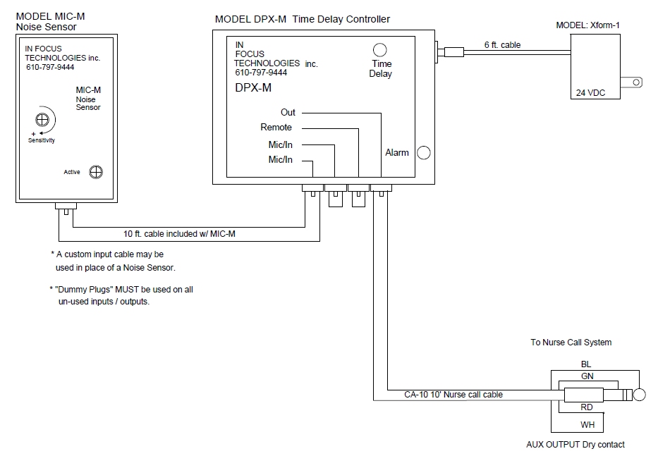
KIT-CA Setup 1. Select a location for the DPX-M, on the monitored device or headwall. Mount to a clean smooth surface with 3m Dual Lock® (included). Check for a secure mounting. 2. Connect remote cable to the PZ-M buzzer, aux. input cable (if included). If any connectors are not used, a dummy plug is required (2 included) to silence the alarm. 3. Plug the MIC-M cable into one of the jacks labeled MIC / IN on the DPX-M. 4. Plug in the 24 volt wall transformer and connect it to the DPX-M. 5. Simulate an alarm condition on the monitored piece of equipment. Determine where the audible alarm is coming from and hold the MIC-M in a position within one to two inches of the noise source. 6. If necessary, gradually increase the sensitivity to a point where a bright steady red light is obtained. Normal setting is 75%-85% of full clockwise. 7. Mount the MIC-M to a clean smooth surface with 3m Dual Lock® and check for a secure mounting. 8. Re-test the setting with an audible alarm. Secure cables with strain relief as required. 9. Simulate an alarm condition and set the time delay on the DPX-M with a small slotted screwdriver. 5 to 15 seconds are typical delays to absorb nuisance alarms. 10. Test that both outputs perform as expected. Remote powers PZ-M buzzer, OUT controls external nurse call (if used). 11. Secure cables as required. Use the strain relief on DPX-M to inhibit accidental plug removal. 12. This system must be tested after each reinstallation and at regular intervals (preferably at the start of each shift).
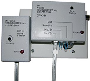
Pictured at right is the ideal
method of mounting the DPX-M time delay and MIC-M noise sensor. A 3 gang plastic electrical plate is mounted
to the wall providing a clean smooth surface. The DPX is held securely with four strips of For Warranty information see; http://www.infocustech.com/warranty.htm
|
© Copyright 2015, InFocusTech.com All rights reserved.


